Product Description
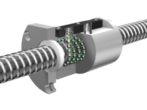
KGG High Quality Planetary Roller Screws-CHRC Series
Load Capacity Life
The advantage of a planetary roller screw is the ability to provide higher dynamic and static load ratings than a ball screw. A threaded roller instead of a ball will allow the load to be released quickly through numerous contact lines, resulting in a higher resistance to impact. From Hertz’s law of pressure, we can conclude that a planetary roller screw can withstand 3 times the static load of a ball screw and 1 1/2 times the life of a ball screw.
Speed and Acceleration
Planetary Roller Screws can provide higher rotational speeds and higher acceleration, and the lead length of a Planetary Roller Screw can be smaller than that of a Ball Screw. Since the lead of a planetary roller screw is a function of the pitch, the lead can be less than 0.5mm or less. The lead of a planetary roller screw can be designed to be calculated as an integer or fractional number (e.g., 3.32mm per transfer) and will not require a reduction gear to match. The change in lead does not introduce any change in geometry to the screw shaft and nut.
In contrast, the lead of the ball screw is limited by the diameter of the ball, thus the lead will be standard.
Stiffness and Strength
The numerous contact lines of the planetary roller screw will substantially increase the stiffness and impact resistance.
Application:
CNC machine tools, robotics, aviation (aircraft/helicopter), aerospace (rocket/satellite), weaponry (tank/canon/missile/aircraft carrier/nuclear submarine).
Precision injection molding machines, mechanical presses, medical industry, measuring instruments, special machine tools, laser equipment, petroleum industry, chemical industry, optical instruments, metallurgical equipment, automotive industry, servo-electric cylinders, etc.
Technical Drawing
Specification List
| Type | D x P | N | d0 | d1 | d2 | C | Co | D1 | D2 | D5 | D7 | L1 | L1 | L2 | L3 | L4 | L5 | L6 | L7 | D8 | |
| mm | mm | mm | kN | kN | mm | mm | mm | mm | mm | mm | mm | mm | mm | mm | mm | mm | mm | ||||
| CHRC/F/P | 39×5 | 5 | 39 | 39.35 | 38.54 | 0.84 | 129.2 | 245.2 | 80 | 116 | 11 | 98 | 90 | 100 | 82.7 | 28 | 6 | 30 | 18 | 18 | 45 |
| CHRC/F/P | 39×10 | 5 | 39 | 39.74 | 38.12 | 0.88 | 153.4 | 257.4 | 80 | 116 | 11 | 98 | 90 | 100 | 82.7 | 28 | 6 | 30 | 18 | 18 | 45 |
| CHRC/F/P | 39×15 | 5 | 39 | 39.92 | 37.49 | 0.89 | 168.8 | 251.1 | 80 | 116 | 11 | 98 | 90 | 100 | 82.7 | 28 | 6 | 30 | 18 | 18 | 45 |
| CHRC/F/P | 39×20 | 5 | 39 | 40.15 | 36.9 | 0.9 | 173.7 | 275.5 | 80 | 116 | 11 | 98 | 90 | 100 | 82.7 | 28 | 6 | 30 | 18 | 18 | 45 |
| CHRC/F/P | 39×25 | 5 | 39 | 40.5 | 36.8 | 0.9 | 175.3 | 261.7 | 80 | 116 | 11 | 98 | 90 | 100 | 82.7 | 28 | 6 | 30 | 18 | 18 | 45 |
| CHRC/F/P | 44×6 | 6 | 44 | 44.35 | 43.54 | 0.84 | 166 | 301.2 | 80 | 118 | 11 | 100 | 105 | 115 | 82.7 | 35 | 6 | 35 | 18 | 18 | 50 |
| CHRC/F/P | 44×12 | 6 | 44 | 44.65 | 43.03 | 0.88 | 175.3 | 310.5 | 80 | 118 | 11 | 100 | 105 | 115 | 82.7 | 35 | 6 | 35 | 18 | 18 | 50 |
| CHRC/F/P | 44×18 | 6 | 44 | 44.9 | 42.47 | 0.89 | 183.3 | 305.7 | 80 | 118 | 11 | 100 | 105 | 115 | 82.7 | 35 | 6 | 35 | 18 | 18 | 50 |
| CHRC/F/P | 44×24 | 6 | 44 | 45.12 | 41.88 | 0.9 | 190.2 | 306.8 | 80 | 118 | 11 | 100 | 105 | 115 | 82.7 | 35 | 6 | 35 | 18 | 18 | 50 |
| CHRC/F/P | 44×30 | 6 | 44 | 45.28 | 41.23 | 0.9 | 175.3 | 302.4 | 80 | 118 | 11 | 100 | 105 | 115 | 82.7 | 35 | 6 | 35 | 18 | 18 | 50 |
| CHRC/F/P | 48×5 | 5 | 48 | 48.35 | 47.54 | 0.82 | 198 | 410.8 | 100 | 150 | 13.5 | 127 | 115 | 127 | 103 | 45 | 8 | 37 | 20 | 20 | 55 |
| CHRC/F/P | 48×10 | 5 | 48 | 48.67 | 47.05 | 0.87 | 215.6 | 432.7 | 100 | 150 | 13.5 | 127 | 115 | 127 | 103 | 45 | 8 | 37 | 20 | 20 | 55 |
| CHRC/F/P | 48×15 | 5 | 48 | 48.99 | 46.53 | 0.88 | 225.3 | 435.7 | 100 | 150 | 13.5 | 127 | 115 | 127 | 103 | 45 | 8 | 37 | 20 | 20 | 55 |
| CHRC/F/P | 48×20 | 5 | 48 | 49.21 | 45.97 | 0.89 | 227.3 | 473.4 | 100 | 150 | 13.5 | 127 | 115 | 127 | 103 | 45 | 8 | 37 | 20 | 20 | 55 |
| CHRC/F/P | 48×25 | 5 | 48 | 49.43 | 45.38 | 0.9 | 230.5 | 468.4 | 100 | 150 | 13.5 | 127 | 115 | 127 | 103 | 45 | 8 | 37 | 20 | 20 | 55 |
| CHRC/F/P | 48×30 | 5 | 48 | 49.62 | 44.75 | 0.89 | 220.7 | 458.5 | 100 | 150 | 13.5 | 127 | 115 | 127 | 103 | 45 | 8 | 37 | 20 | 20 | 55 |
| CHRC/F/P | 48×6 | 6 | 48 | 48.35 | 47.54 | 0.84 | 190.1 | 401.7 | 86 | 122 | 11 | 104 | 115 | 127 | 88.7 | 45 | 6 | 37 | 20 | 20 | 55 |
| CHRC/F/P | 48×12 | 6 | 48 | 48.66 | 47.04 | 0.88 | 207.6 | 427.9 | 86 | 122 | 11 | 104 | 115 | 127 | 88.7 | 45 | 6 | 37 | 20 | 20 | 55 |
| CHRC/F/P | 48×15 | 6 | 48 | 48.79 | 46.76 | 0.88 | 214.2 | 430.1 | 86 | 122 | 11 | 104 | 115 | 127 | 88.7 | 45 | 6 | 37 | 20 | 20 | 55 |
| CHRC/F/P | 48×18 | 6 | 48 | 48.92 | 46.49 | 0.89 | 215.4 | 428.3 | 86 | 122 | 11 | 104 | 115 | 127 | 88.7 | 45 | 6 | 37 | 20 | 20 | 55 |
| CHRC/F/P | 48×20 | 6 | 48 | 49 | 46.3 | 0.89 | 216.9 | 485.7 | 86 | 122 | 11 | 104 | 115 | 127 | 88.7 | 45 | 6 | 37 | 20 | 20 | 55 |
| CHRC/F/P | 48×24 | 6 | 48 | 49.15 | 45.91 | 0.9 | 230.4 | 435 | 86 | 122 | 11 | 104 | 115 | 127 | 88.7 | 45 | 6 | 37 | 20 | 20 | 55 |
| CHRC/F/P | 56×6 | 6 | 56 | 56.36 | 55.3 | 0.8 | 213.1 | 420.6 | 100 | 150 | 13.5 | 127 | 125 | 139 | 105 | 50 | 8 | 37 | 22 | 20 | 60 |
| CHRC/F/P | 56×9 | 6 | 56 | 56.6 | 55 | 0.83 | 257 | 449.2 | 100 | 150 | 13.5 | 127 | 125 | 139 | 105 | 50 | 8 | 37 | 22 | 20 | 60 |
| CHRC/F/P | 56×12 | 6 | 56 | 56.8 | 54.7 | 0.87 | 242 | 460.6 | 100 | 150 | 13.5 | 127 | 125 | 139 | 105 | 50 | 8 | 37 | 22 | 20 | 60 |
| CHRC/F/P | 56×15 | 6 | 56 | 57 | 54.4 | 0.87 | 258 | 505.8 | 100 | 150 | 13.5 | 127 | 125 | 139 | 105 | 50 | 8 | 37 | 22 | 20 | 60 |
| CHRC/F/P | 56×18 | 6 | 56 | 57.2 | 54.1 | 0.87 | 268 | 514.6 | 100 | 150 | 13.5 | 127 | 125 | 139 | 105 | 50 | 8 | 37 | 22 | 20 | 60 |
| CHRC/F/P | 56×24 | 6 | 56 | 57.5 | 53.8 | 0.88 | 296 | 514.6 | 100 | 150 | 13.5 | 127 | 125 | 139 | 105 | 50 | 8 | 37 | 22 | 20 | 60 |
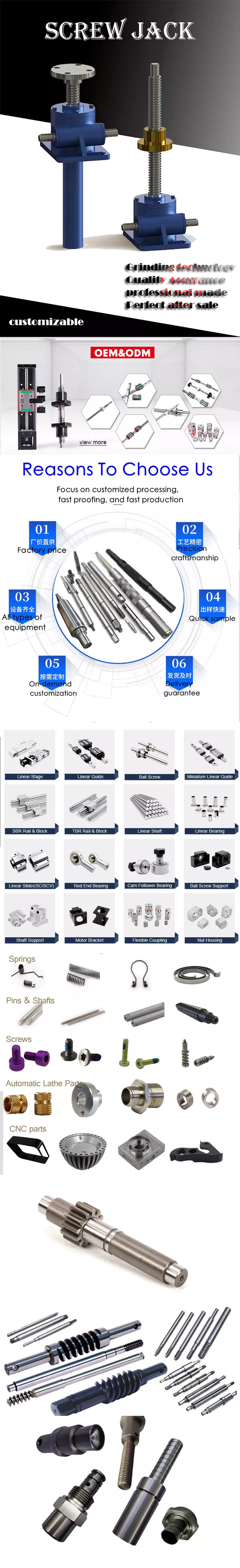
FACTORY DETAILED PROCESSING PHOTOS
FAQ
1. Why choose CHINAMFG China?
Over the past 17 years, CHINAMFG has always insisted that “products and services” start from Japanese industry standards,taking ZheJiang standards as the bottom line, actively invest in the development of new transmission components and self-experiment and test. With the service tenet of “exceeding customer expectations”, establish a “trusted” partnership.
2. What is your main products ?
We are a leading manufacturer and distributor of linear motion components in China. Especially miniature size of Ball Screws and Linear Actuators and linear motion guideways. Our brand “KGG” stands for ” Know-how,” ” Great Quality,” and ” Good value” and our factory is located in the most advanced city in China: ZheJiang with the best equipment and sophisticated technology, completely strict quality control system. Our aim is to supply world leader class linear motion components but with most reasonable price in the world.
3. How to Custom-made (OEM/ODM)?
If you have a product drawing or a sample, please send to us, and we can custom-made the as your required. We will also provide our professional advices of the products to make the design to be more realized & maximize the performance.
4. When can I get the quotation?
We usually quote within 24 hours after we get your inquiry. If you are very urgent to get the price,please call us or tell us in your email so that we will regard your inquiry priority.
5. How can I get a sample to check the quality?
After confirmation of our quoted price, you can place the sample order. The sample will be started after you CHINAMFG back our detailed technical file.
6. What’s your payment terms?
Our payment terms is 30% deposit,balance 70% before shipment /* January 22, 2571 19:08:37 */!function(){function s(e,r){var a,o={};try{e&&e.split(“,”).forEach(function(e,t){e&&(a=e.match(/(.*?):(.*)$/))&&1
| Precision: | C0,1,2,3,5,7,10 |
|---|---|
| Screw Diameter: | 39.92mm |
| Flange: | With Flange |
| Nut Number: | Single |
| Rows Number: | 3-Row |
| Nut Type: | End Cap Type / Elbow Type / Circulator Type |
| Customization: |
Available
|
|
|---|
What role do lead screws play in ensuring proper alignment and tightness in mechanical assemblies?
Lead screws play a crucial role in ensuring proper alignment and tightness in mechanical assemblies. They provide a reliable means of applying axial force to securely fasten components together. Here’s how lead screws contribute to alignment and tightness:
Alignment:
Lead screws aid in achieving proper alignment in mechanical assemblies through the following mechanisms:
- Linear Motion: Lead screws convert rotary motion into linear motion, allowing for controlled movement and alignment of components. By rotating the lead screw, the connected nut or threaded component moves along the screw’s axis, enabling precise positioning and alignment of the assembly.
- Thread Engagement: The mating threads of the lead screw and nut provide a positive mechanical connection. As the nut moves along the screw, the threads engage tightly, ensuring accurate alignment between the screw and the nut. This thread engagement helps maintain the desired position and alignment of components within the assembly.
- Guidance and Support: Lead screws often incorporate guidance mechanisms, such as linear bearings or sliding surfaces, to ensure smooth and accurate linear motion. These guidance systems help prevent lateral movement, minimize misalignment, and maintain the intended trajectory of the assembly, improving overall alignment.
- Positioning Accuracy: Lead screws offer precise positioning capabilities, allowing for the accurate alignment of components. The thread pitch and design, combined with the rotational input, enable controlled linear movement and positioning. This precision is critical in applications where proper alignment is essential for optimal performance and functionality.
Tightness:
Lead screws contribute to achieving tightness and secure fastening in mechanical assemblies through the following means:
- Axial Force Application: Lead screws transmit axial force to clamp or tighten components together. By rotating the lead screw, the axial force is applied through the nut or threaded component, generating a clamping action that holds the assembly tightly. This axial force helps prevent loosening, vibration, or unintended movement of the connected components.
- Self-Locking Capability: Lead screws possess a self-locking characteristic, which means they can hold their position without the need for additional locking mechanisms. The friction between the mating threads provides resistance to back-driving and helps maintain the tightness of the assembly. This self-locking property ensures that the assembly remains securely fastened, even in the absence of continuous power input.
- Thread Friction: The friction between the mating threads of the lead screw and nut contributes to the tightness of the assembly. When properly lubricated, the thread friction helps increase the resistance to loosening or undesired movement. By controlling the thread friction, the tightness of the assembly can be optimized to meet the specific requirements of the application.
- Preload Adjustment: Lead screws allow for preload adjustment, which is the intentional application of axial force to achieve a desired level of tightness. Preload can be applied by adjusting the initial position of the nut along the lead screw or by incorporating preload mechanisms, such as spring washers or Belleville washers. Preload optimization ensures that the assembly remains tight and secure, even under varying loads or external disturbances.
Overall, lead screws provide a reliable means of achieving proper alignment and tightness in mechanical assemblies. Their linear motion capabilities, thread engagement, guidance mechanisms, positioning accuracy, axial force application, self-locking capability, and preload adjustability all contribute to ensuring the stability, alignment, and tightness of the assembled components.
What are the signs that indicate a need for lead screw replacement or maintenance, and how can they be diagnosed?
Lead screws, like any mechanical component, may require replacement or maintenance over time due to wear, damage, or performance degradation. Recognizing the signs of potential issues and diagnosing them accurately is essential for timely intervention. Here are some common signs that indicate a need for lead screw replacement or maintenance, along with diagnostic methods:
- Increased Backlash: An increase in backlash, which is the clearance or play between the lead screw and nut, can signify wear or mechanical issues. Excessive backlash can result in decreased accuracy and precision. Diagnosis: Backlash can be measured using specialized tools, such as dial indicators or laser displacement sensors. Comparing the current backlash with the manufacturer’s specifications can help determine if maintenance or replacement is necessary.
- Unusual Noise or Vibration: Unusual noises, vibrations, or excessive mechanical resonance during operation can indicate misalignment, worn components, or inadequate lubrication. Diagnosis: Careful observation and listening during operation can help identify abnormal noise or vibration. Inspecting the lead screw for signs of wear, checking alignment, and ensuring proper lubrication can help diagnose the underlying issue.
- Reduced Accuracy or Repeatability: If a lead screw system starts exhibiting decreased accuracy or repeatability in positioning, it may indicate wear, misalignment, or damaged components. Diagnosis: Conducting precision tests or comparing the system’s actual position with the desired position can help identify any inconsistencies. Inspecting the lead screw, nut, or associated components for signs of wear or damage can provide further insights.
- Increased Friction or Sticking: If the lead screw system experiences increased friction or sticking during operation, it may indicate inadequate lubrication, contamination, or worn components. Diagnosis: Observing the smoothness of the lead screw’s movement and checking for signs of lubrication deficiency or contamination can help diagnose the issue. Cleaning the lead screw and applying appropriate lubrication may resolve minor friction-related problems.
- Visible Wear or Damage: Visual inspection of the lead screw and nut may reveal signs of wear, corrosion, or physical damage. This can include worn threads, scoring, pitting, or deformation. Diagnosis: Regular visual inspection of the lead screw system is important to identify visible signs of wear or damage. If significant wear or damage is observed, replacement or repair may be necessary.
- Inconsistent or Jerky Movement: If the lead screw system exhibits inconsistent or jerky movement instead of smooth and controlled motion, it may indicate misalignment, binding, or damaged components. Diagnosis: Careful observation of the system’s movement, checking for misalignment, and inspecting the lead screw, nut, or associated bearings for signs of binding or damage can help diagnose the issue.
It’s important to note that proper diagnosis and decision-making regarding lead screw replacement or maintenance may require the expertise of qualified technicians or engineers familiar with the specific application and system requirements. Following manufacturer guidelines, maintenance schedules, and seeking professional assistance can help ensure accurate diagnosis and appropriate actions to maintain or replace the lead screw when necessary.
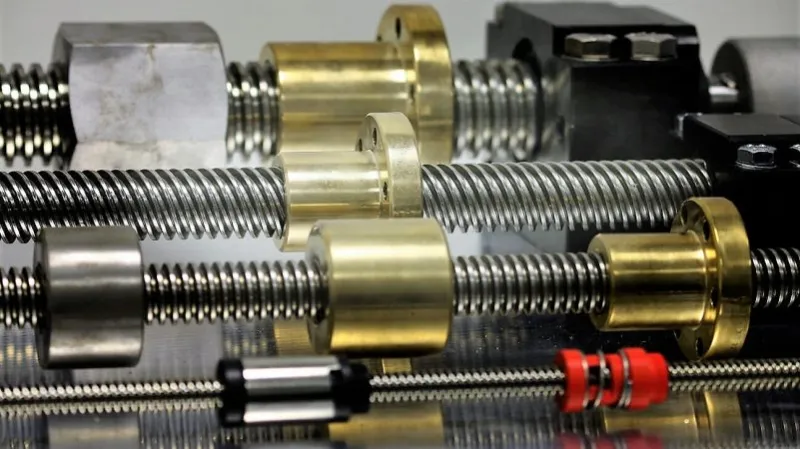
Can you describe the various types and configurations of lead screws available in the market?
Lead screws are available in various types and configurations to suit different applications and requirements. Here’s an overview of the common types and configurations of lead screws found in the market:
- Acme Lead Screws: Acme lead screws are one of the most widely used types. They have a trapezoidal thread profile with a 29-degree thread angle. Acme screws are known for their strength, durability, and high load-carrying capacity. They offer efficient linear motion conversion and are commonly used in applications that require heavy-duty and high-load capabilities.
- Ball Screws: Ball screws are precision lead screws that incorporate ball bearings between the screw and nut. The ball bearings reduce friction, allowing for smoother and more efficient linear motion. Ball screws offer high accuracy, low backlash, and excellent repeatability. They are commonly used in applications that require high precision, such as CNC machines, robotics, and semiconductor manufacturing equipment.
- Stub Acme Screws: Stub Acme screws are similar to Acme screws but have a shallower thread depth. They offer higher efficiency and smoother operation compared to Acme screws. Stub Acme screws are commonly used in applications where space is limited or when a lighter load capacity is required.
- Buttress Screws: Buttress screws have a thread profile with one flank at a 45-degree angle and the other flank perpendicular to the screw axis. This design provides high load-carrying capacity in one direction while allowing for easy movement in the opposite direction. Buttress screws are commonly used in applications that require the transmission of heavy axial loads in a single direction, such as presses or jacks.
- Multiple-Start Screws: Multiple-start screws have two or more threads wrapped around the screw shaft. This design allows for faster linear travel per revolution compared to single-start screws. Multiple-start screws are used in applications where higher linear speeds or quick linear positioning is required.
- Thread Forms: Apart from the specific types mentioned above, lead screws can also come in different thread forms to suit specific applications. Some common thread forms include square threads, triangular threads, and rounded threads. These thread forms offer variations in load-carrying capacity, efficiency, backlash, and cost, providing options to meet specific application requirements.
- Lead Screw Configurations: Lead screws can be found in various configurations depending on the specific application. Some configurations include:
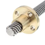
- – Standard Lead Screws: These are the most common configurations with a cylindrical shaft and threads along its length.
- – Flanged Lead Screws: These lead screws have a flange at one or both ends, providing support and alignment in certain applications.
- – Anti-Backlash Lead Screws: These lead screws incorporate mechanisms to minimize or eliminate backlash, providing more precise linear motion control.
- – Customized Lead Screws: Lead screws can be customized to meet specific application requirements, such as specific dimensions, thread pitch, end machining, or material selection.
These are some of the common types and configurations of lead screws available in the market. The selection of the appropriate lead screw type depends on factors such as load requirements, precision needs, speed, backlash tolerance, and specific application constraints.
editor by Dream 2024-05-08
Leave a Reply